The
Robotics
Interface
Page

        
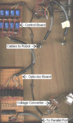
Photo of the Interface Prototype


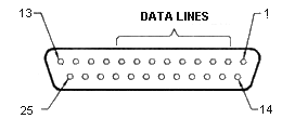
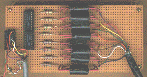
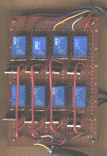
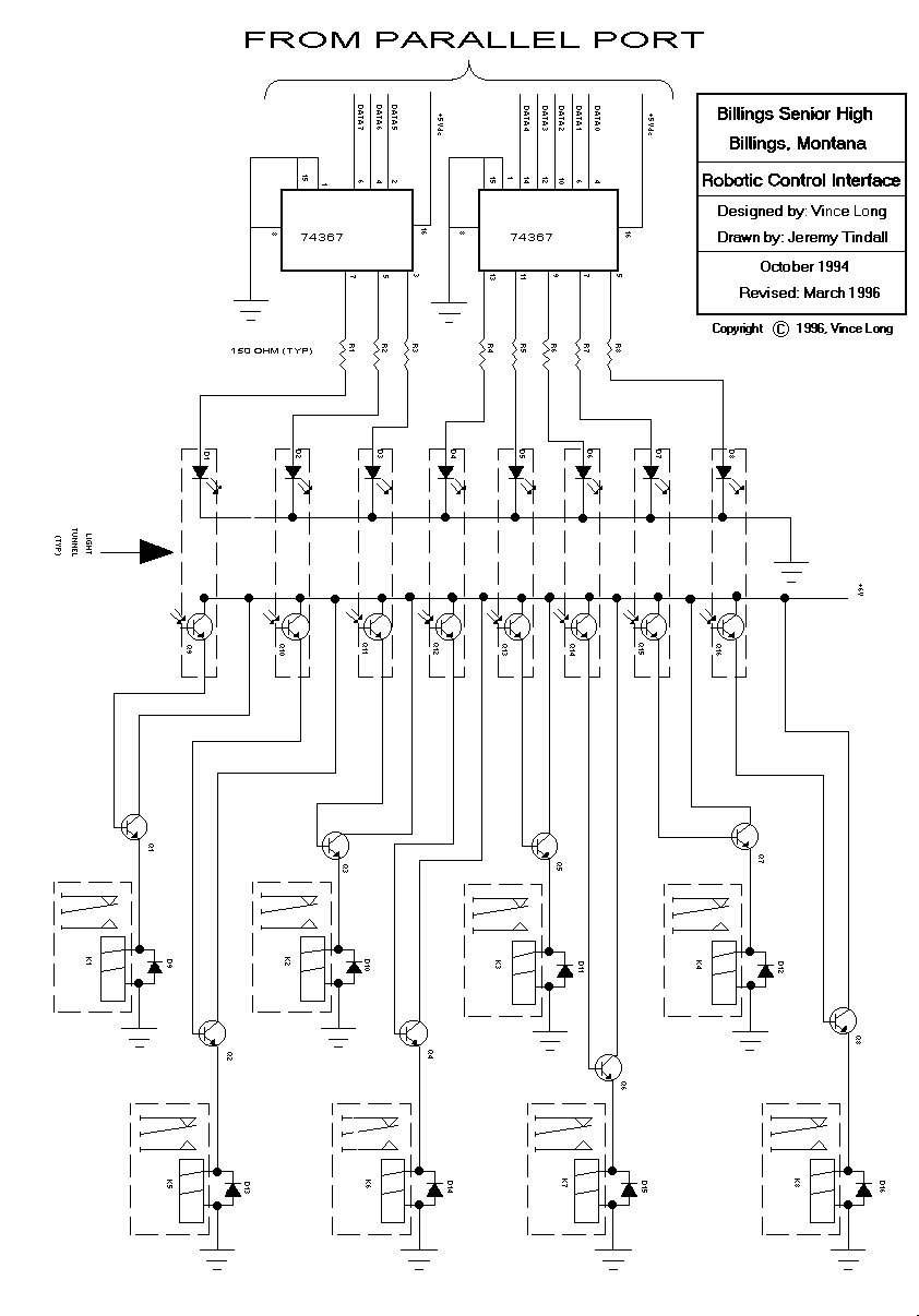
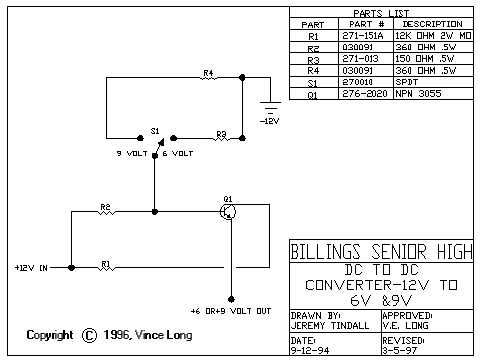
On this page you will find a complete description of a robotics interface that you can easily build to control external electrical devices using any DOS-based PC as the programmable controller.

Background - Overview of the Interface - The Software - Schematics


Background

Several years ago I became interested in using an old, XT-class PC as a programmable device to control the movements of a robot. I had read that the data lines on the parallel port could be controlled using GW-BASIC, a language that came with every PC sold. So, after doing a fair amount of research, I came up with the design that is shown on this page.

The interface allows the control of up to eight devices at one time. The limit of eight was selected because this is the number of data lines from the parallel port. Most ports have a few additional lines but I have elected not to utilize them in this design.

Right off I should tell you that I know that this device could be built with far fewer parts than I have included in my design. In fact, I have built a "version 2" that only uses 4 parts per channel. However, this first version of the interface grew out of my exploration of optical isolation, fiber optics, and my need to demostrate these topics to my students.

I make no attempt here to explain the inner workings of the electronics or detail any construction techinques. I assume that the reader can find that information elsewhere.


Overview of the Interface

The interface consists of two separate boards, though they could be built on a common platform. The first board, the OPTO board, handles the problem of keeping the robot isolated from the computer. If the robot went crazy and stuft its hand in a power outlet, I wanted to avoid allowing that current from finding its way back to my computer's motherboard via the parallel port.

The second board, CONTROL, contains the relays that will open and close, on command, and therefore, switch current to the motors, or other devices, on the robot.

The OPTO Board
The OPTO board has two sections. The first contains two 74376 ICs. The function of these chips is to allow the LEDs to be turned on using the current from the computer's power supply rather than the signal from the parallel port. The parallel port signal is only used to trigger the transistors in the chips.

The second section of the OPTO board contains 8 infrared LED/phototransistor pairs. These are mounted in a drilled-out wooden dowel and are pointed at each other. They are physically separated by about 1/4 inch inside the dowel. I found it necessary to wrap the dowels with black electrical tape to prevent outside light from producing false signals.

The CONTROL Board
This board contains a power transistor and a relay for each channel. The base connection on the power transistor is connected to the phototransistor on the OPTO board. When the infrared beam strikes the phototransistor, the resistance across it changes, allowing a current to flow to the base connection on the power transistor. This, in turn, allows a current to flow through the collector-emmitter circuit of the power transistor which flows through the coil of the relay, causing the relay to close.

In an earlier design, one that I had seen in a handbook from a popular electronics retailer, a 2222 transistor was shown to be sufficient in this application. I found it necessary to use the 3055 transistor to get enough current to the coil of the relay. The diode that is placed across the coil of the relay is to prevent any high voltage, induced by the collapsing magnetic field in the coil, from damaging the rest of the circuit.

The Voltage Converter
The Voltage Converter, shown in the separate schematic, is used to convert 12 volts from the computer's power supply to 6 volts, which is used to operate the interface. I put a pair of jacks on the back of the computer that I can use to pick up 5 or 12 volts from the power supply.

The Robot
I used a toy robot in my initial design. Any electrical device or collection of devices could be used. Just keep in mind that the contacts in the relay have an amperage rating that should not be exceeded.


The Connections

Connecting the interface to the computer is done using a DB25 connector, which matches that on the computer's parallel port. Be sure to route the wires to the correct pin.


The diagram, above, shows the pin numbering scheme for the connector. It is only necessary to connect to the 8 data lines and the ground.

The pin assignments are shown in the table, below:

Pin Number Function
1 -Strobe
2 Data 0
3 Data 1
4 Data 2
5 Data 3
6 Data 4
7 Data 5
8 Data 6
9 Data 7
10 -Ack
11 +Busy
12 Paper End
13 +Selectln
14 -AutoFd
15 -Error
16 -Init
17 -Select
18-25 Ground


How the connection is made to the robot will depend on the robot. I rewired mine to accept two DB9 connectors, but a DB25 or any other connector could be used.


The Software

The software to operate the interface can easily be written in BASIC. Older DOS machines came with GW-BASIC, while newer machine have Q-BASIC. The programs shown here can be entered in either language. Windows programs, such as Visual BASIC, cannot be used as Windows addresses the parallel port in a different way.

I have included two programs, below. The first, COUNTER.BAS, can be used to test the interface. You can replace the IR-LEDs with visible LEDs and watch the LEDs illuminate as the program counts from 1 to 255. If the entire interface is connected, the relays will "click" in turn as they are energized.

In the second program, INNUMOUT.BAS, the user is prompted to enter a number and that number is sent to the parallel port, energizing 1 or more channels. In practice, I only energize one channel at a time. The numbers to output to turn on the individual channels (relays) are shown below:

Relay to turn On Number to Output
Kl 1
K2 2
K3 4
K4 8
K5 16
K6 32
K7 64
K8 128


To activate more than one relay at a time, add their decimal number together and enter the sum into the INNUMOUT.BAS program.

COUNTER.BAS - Sample Program for Testing the Interface

10 REM This program, COUNTER.BAS, will test the interface sending the
15 REM decimal values of 1 through 255 to the printer port
20 GOTO 100 : REM Goto program start
30 REM Begin the Subroutine
35 OUT 888,0 : REM Turns off the data lines
40 FOR I = 1 TO 255 : REM Begin the loop
45 LOCATE 10, 1 : PRINT I : REM Positions the Cursor and Shows value of I
50 OUT 888,I : REM Sends the value of I to LPT1
55 FOR D = 1 TO 250: NEXT D : REM Delay Loop
60 NEXT I : REM Restart loop
65 OUT 888,0 : REM Turns off the data lines
70 RETURN : REM Ends the Subroutine
100 REM Begin the main part of the program
110 CLS : REM Clears the screen
120 LOCATE 5,1 : PRINT "Counting from 1 to 255" : REM Puts message on screen
130 GOSUB 30 : REM Start the subroutine
140 LOCATE 1O, 1 : PRINT " " : REM Clear screen
150 GOTO 130 : REM Start over


INNUMOUT.BAS - Sample Program to allow the user to output specific decimal numbers to the interface

1O REM This program will send a decimal number to the printer port
20 REM The program name is INNUMOUT.BAS
30 CLS : REM This line clears the screen
40 OUT 888,0 : REM This line turns off all the data lines on LPT1
50 INPUT "Enter the number to output ";X
60 PRINT : PRINT "Sending ->:;X;" <- to LPT1" : REM Send a message to the screen
70 OUT 888,0 : REM This line turns off all the data lines on LPT1
80 OUT 888,X : REM Sends the value of X to LPT1
90 GOTO 30 : REM Sends program to ask for a new value of X


If you have any questions or comments, feel free to e-mail me:vince@codecooker.com


Schematics
The Board Overall photo of the interface prototype. Major parts are labelled. (55 K)
The OPTO Board. Photo of the OPTO board. (28 K)
CONTROL Board Photo of the CONTROL board. (20 K)
Schematic of the Interface Schematic of the OPTO and CONTROL boards. (34 K)
Parts List for the Interface A parts list for the interface.
Schematic of the Voltage Converter Schematic of the voltage converter board. (34 K)


Back to the Main Robotics Page


Copyright © 1997, Vince Long